A typical situation with SDR receivers is the presence of the zero frequency or ‘DC’ artifact in the receiver output. The artifact shows up as a zero frequency spike in the FFT, a zero frequency line on the waterfall, or an audible heterodyne on the received carrier. This artifact can be removed from the receive passband by implementing frequency offsets into the receiver front end. A typical SDR receiver flow graph consists of a Source followed by a Freq Xlating FFT Filter. Large frequency changes are usually made by center frequency parameters in the Source Properties box and small ‘tuning’ changes by center frequency parameters in the Frequency Xlating FFT Filter Properties box.

The zero frequency artifact is removed with identical differential offsets to the RF frequency of the Source and the baseband frequency of the Frequency Xlating FFT Filter. In this manner the zero frequency is offset by an arbitrary amount and yet the received signal remains in the center of the receive passband. The following series of FFT GUI’s and Properties boxes will illustrate the solution.


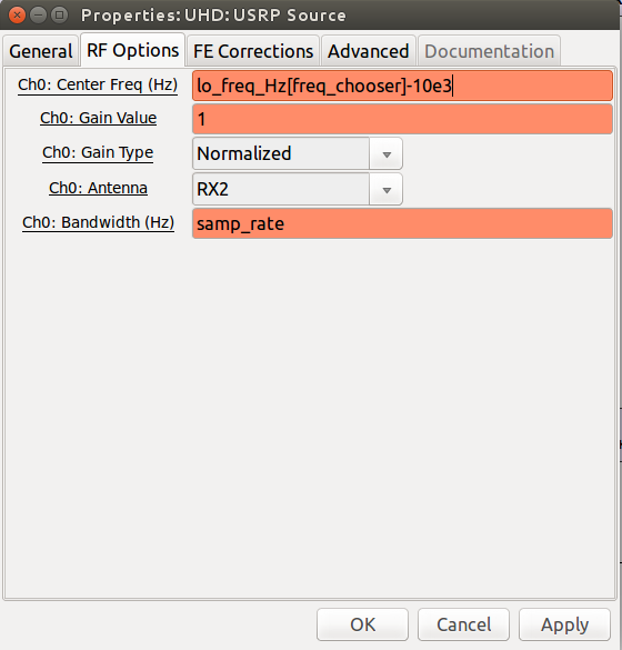
Note the ‘Center Frequency’ text boxes with the notation ‘0’ included in each of the Parameter boxes. Both the Source and the FFT Filter are not offset. The artifact appears in the passband output.

FFT GUI that illustrates the 10 kHz offset achieved by equal and opposite frequency inputs to the RF and baseband SDR front end


Note the ‘Center Frequency’ text boxes with the notation ’10e3′ included in each of the Parameter boxes. These Center Frequency parameters determine the 10 kHz offset. In this case, the Source is offset -10 kHz, and the FFT Filter is offset +10 kHz. These frequency values and the sign of the offset can be varied to suit the application.
Link to Terms and Abbreviations Page: Terms and Abbreviations
Home Page link: Home Page