GPIO control of SDR RF peripherals is very useful for SDR station building. There are any number of RF peripherals that need control for TX and RX functions: antenna relays, sequencers, RX pre-amplifiers, TX power amplifier PTT, and other system functions. There is a simple and direct method to achieve GPIO control of these functions within a GNU Radio flowgraph. The goal is for all of the peripherals to transition from receive to transmit status at the same time the transceiver flow graph makes the same transition. How to achieve that? An approach is to tap into the GPIO control of the SDR onboard status LED’s.
Advanced SDR hardware boards, typically, incorporate LEDs to indicate the transceiver status: green LED for receive and a red LED for transmit. The small amount of current from the on-board status LEDs can be used to activate an intermediate relay. The intermediate relay will, in turn, control the peripherals. One left click in the Operating GUI and the flow graph and the entire station can change from the receive to the transmit state. I choose the red transmit LED for my circuits. A simple circuit schematic is depicted below.
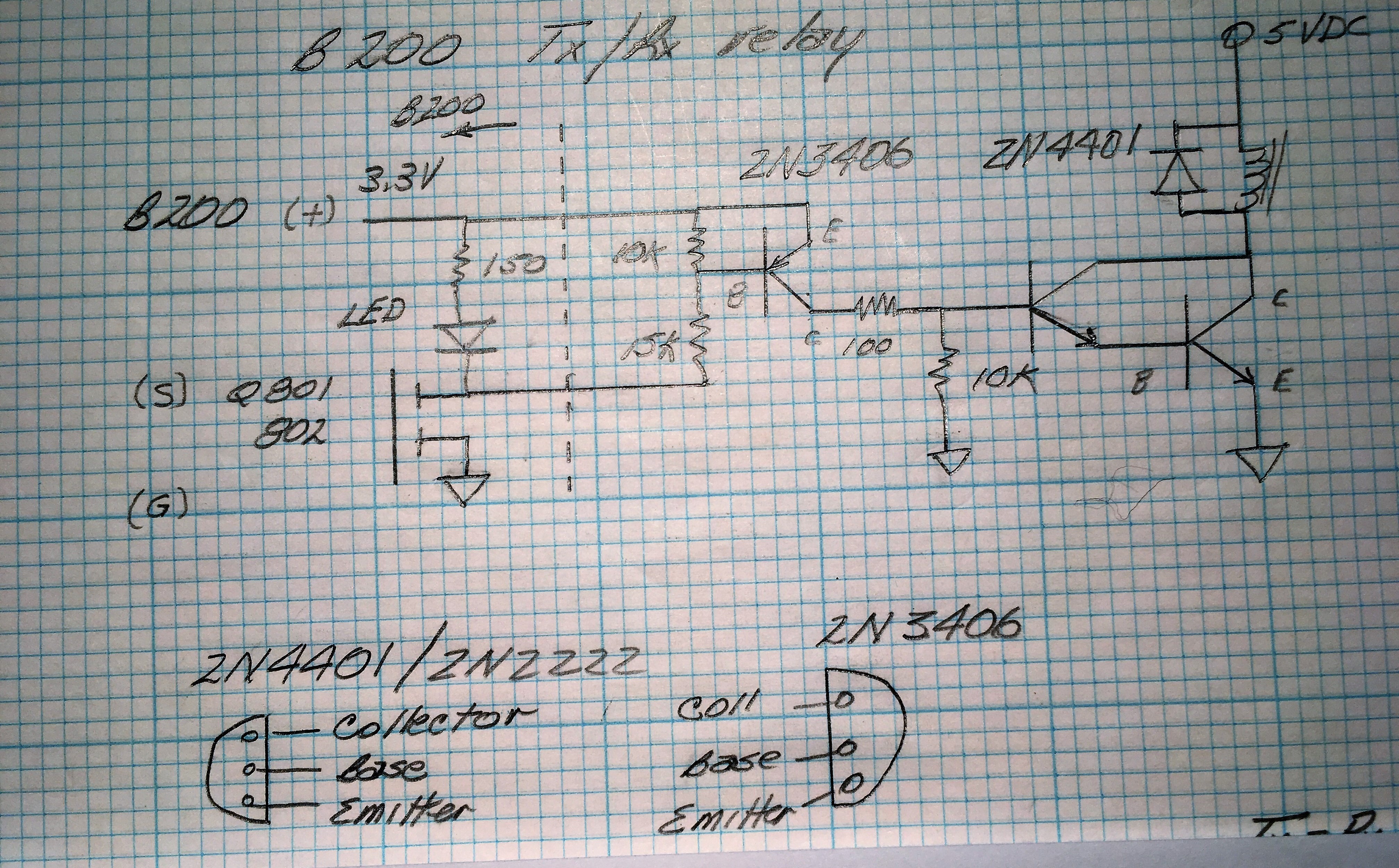
The components are mounted on a small piece of Vector board. The transistor configuration will reflect the desired gain necessary to drive the intermediate relay that is used. The small module is mounted close to the SDR board to minimize accidental common mode pickup from the connecting wiring.

Link to Terms and Abbreviations: Terms and Abbreviations
Link to Home Page: Home Page