This project describes experiments with two 10 GHz transceivers that utilize the dual transceiver capabilities of the RFIC in two different ways. The foundational concept is to use one of the RFIC transceivers for the IF function and use the second RFIC transceiver function as the LO for the 10 GHz mixer.
The first project to be presented utilizes the 5 GHz native tuning range of the RFIC transceivers to provide direct 5 GHz IF and LO input to a microwave mixer for 10 GHz operation. This approach had it’s inspiration from Matt Reilly, KB1VC: SoDa Radio The second project utilizes the dual transceiver approach, but operates at 1.3 GHz. One transceiver generates a ~1.3 GHz signal that is multiplied to ~9 GHz for the LO input to the 10 GHz mixer. The other transceiver implements a 1.3+GHz IF transceiver to the IF port of the 10 GHz mixer. The result after mixing is a 10 GHz transceiver. By capitalizing on the dual transceiver approach, the same high quality, low phase noise synthesizer in the RFIC is used in both the IF and LO. The result is to consolidate the IF and LO connections to a transverter into a single SDR package.
The dual transceiver approach with split frequencies is simple to explain. Review of an advanced SDR block diagram that shows the RFIC analog front end followed by the FPGA and the data stream outputting to the data interface.
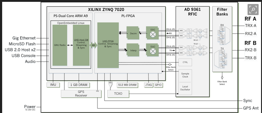
The synthesizer implemented within the AD 9361 dual transceiver RFIC controls both transceivers and directs them to the same frequency. For split frequency operation, the FPGA Numerically Controlled Oscillator (NCO) for each channel is programmed in the GNU Radio flowgraph to offset the frequency of operation of each transceiver. The frequency offset potential is in turn determined by the FPGA clock frequency. The offset frequency between the two transceivers is limited to1/2 of the clock frequency each side of the center synthesizer frequency. The Ettus B210, with it’s 32 MHz clock, puts an upper limit of +/-15 MHz offset for each transceiver. A +/- 13 MHz offset was chosen for this application to avoid problems from alias signals.
5 GHz LO and IF
The first project utilizes the native functionality of the SDR station to produce 5 GHz split frequency signals for both the IF and LO of the 10 GHz transverter. This approach is illustrated here in two different renditions. The photo below illustrates the final rendering of the transverter, as it is used in practice. The second photo illustrates the ‘bare bones’ minimal approach to illustrate the principle and was used as proof of concept.
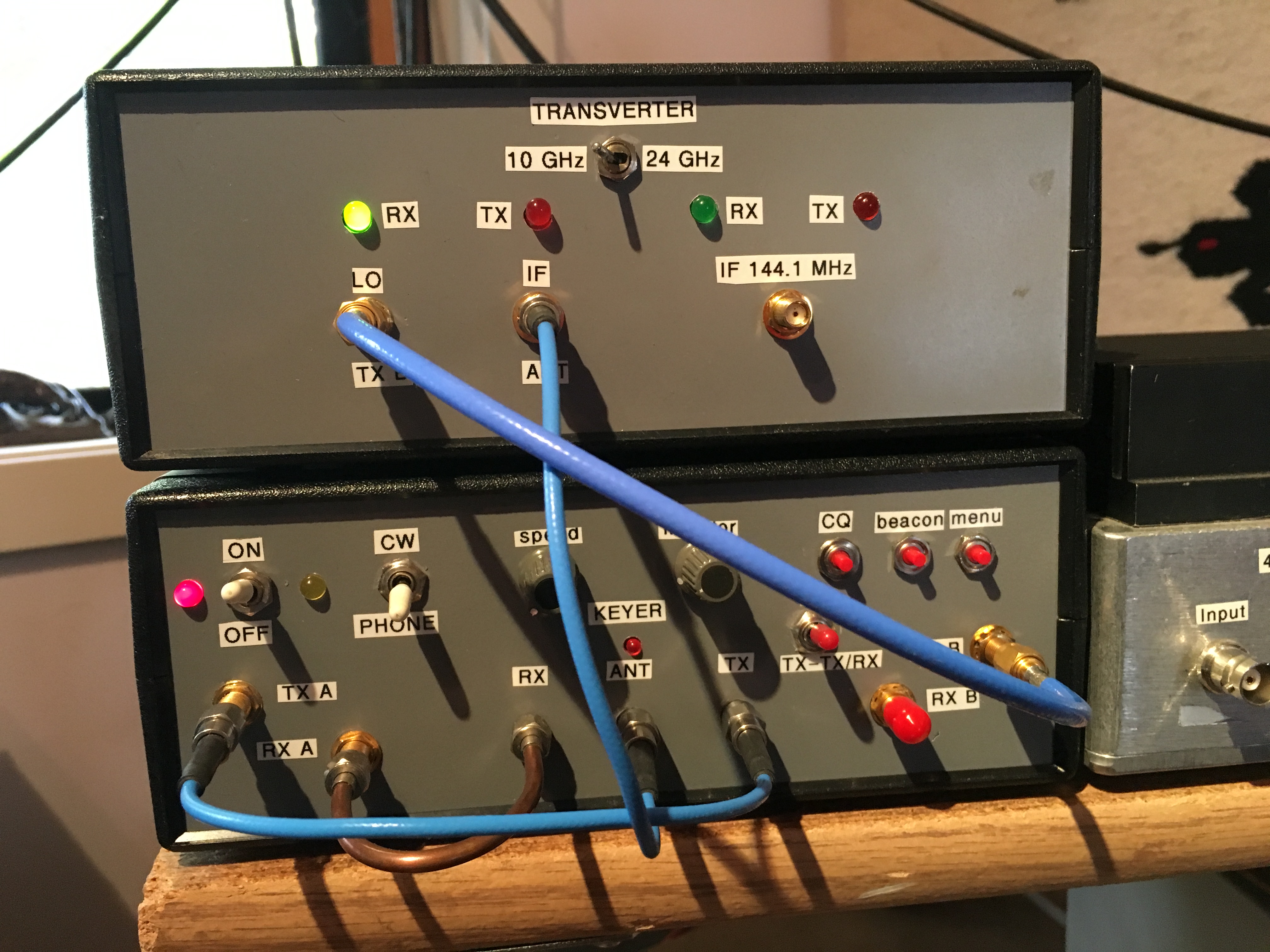
Examine the front panels of the VHF / Microwave SDR station and 10 GHz transverter pictured below. This is a photo of the complete dual transceiver approach in practice. The photo shows two enclosures stacked on one another. The upper enclosure houses the 10 GHz transverter. The transverter enclosure houses the 10 GHz mixer, the receive pre-amplifier, transmit amplifier chain and change over relays to implement a 100 mW 10 GHz transceiver. The bottom enclosure houses the VHF / Microwave SDR station with the built in RF interface and built in assorted station peripherals such as the CW keyer, beacon keyer, sequencer, and internal 10 MHz precision OCXO. In other words, a ‘station’.
The the front panel of the SDR station is divided in the middle by the microwave T/R relay. To the left of the relay are the transmitter and receiver ports for transceiver “A”. To the right of the relay are the transmitter and receiver ports for transceiver “B”. Tracing the coaxial cables from the SDR you can see that the transmitter output from transceiver “A” (offset frequency at 5 GHz) connects to the TX port of the T/R relay. The receiver input for transceiver “A” connects with hard-line to the RX port of the T/R relay. The “Ant” port of the T/R relay connects via a blue colored coaxial cable to the “IF” connector on the transverter. The transmitter output of transceiver “B”, (the 5 GHz offset LO signal to the mixer) connects via a blue colored coaxial cable to the LO input port on the transverter. The result is that transceiver “A” of the SDR functions as the IF through the T/R relay. The transmitter portion of transceiver “B” supplies the offset LO for the transverter. The receiver portion of transceiver “B”, the coaxial connector with the red cap, is not used in this particular application.
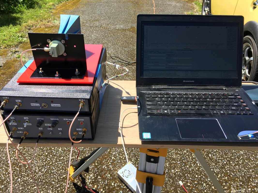
The bottom line is a compact and portable 10 GHz SDR station ready for fixed station or rover operation.
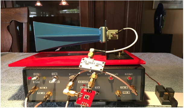
The next photo is of the ‘bare bones’ mixing system that is the heart of the complete 10 GHz transverter pictured above. This photo also illustrates the interconnections that link the VHF / Microwave SDR station and the 10 GHz mixer. The T/R relay “ANT” port connects transceiver “A” to the mixer IF port to provide the offset 5 GHz IF. The transmitter output from transceiver “B” , off set 5 GHz signal, connects to the mixer LO port. The mixer RF port connects via a bandpass filter to the 10 GHz horn antenna. The end result is a 10 GHz transceiver that utilizes the dual transceiver in the SDR station to generate offset 5 GHz IF and LO signals that mix to 10 GHz.
The GNU Radio flowgraph for this project is best reviewed by downloading and executing the .grc file. By downloading and viewing the flowgraph on your computer screen, it is easier to view the entire flowgraph and examine the DSP block parameters in detail. The link to the .grc file for this project is here: 10 GHz Dual Transceiver SDR, 5 GHz IF and LO
1.3 GHz IF and 9 GHz LO
Another method to leverage the SDR station dual transceiver capability for a 10 GHz transverter is to offset the transceivers at 1.3 GHz. With this approach, transceiver “A” provides the offset 1.3 GHz IF and transceiver “B” provides an offset 1.3 GHz LO signal. The offset 1.3 GHz signal from transceiver “B” is in turn multiplied by 7 to provide a 9 GHz LO input to the 10 GHz mixer. This approach implements a rather conventional 10 GHz mixer approach with an internal bandpass filter that removes the LO signal and mixing image signal from the 10 GHz input/output. Illustrations of this approach are in the photos below.
With this transverter design, the transceiver “B” transmitter output, the offset 1.3 GHz signal from the coax connector located on the right edge of the SDR station front panel, is connected directly to the 7X LO multiplier inside the transceiver enclosure. The “B” transceiver output to the 7X multiplier results in the 9 GHz LO signal to the 10 GHz mixer. The transmitter and receiver ports for Transceiver “A”, located on the left edge of the SDR station front pane, the offset IF at 1.3 GHz, are connected to the transmitter and receiver ports of the 10 GHz transverter. The transceiver ports are switched internally to the mixer IF port.
The GNU Radio flowgraph for this project is best reviewed by downloading and executing the .grc file. By downloading and viewing the flowgraph on your computer screen, it is easier to view the entire flowgraph and examine the DSP block parameters in detail. The link to the .grc file for this project is here:10 GHz Dual Transceiver SDR 1.3 GHz IF and LO
Link to Terms and Abbreviations: Terms and Abbreviations
Link to Home Page: Home Page