A 9-band Multi mode SDR station: VHF through Microwave
The Project: Build a homebrew multi band VHF/ microwave transceiver with exceptional RF performance characteristics based on SDR technology.
Result: The initial multi band VHF/microwave SDR transceiver project grew over time to become a homebrew, portable 9-band multi mode VHF/microwave SDR station for fixed and rover operation from 50 MHz thorough 5.7 GHz. The station can be configured to function as a standalone QRP SDR station, a foundational transceiver and control system for higher performance microwave radio systems, and, for test and measurement, a useful microwave spectrum analyzer and signal source. The same excellent radio performance can be extended to the higher microwave and mmWave bands with transverters that use the 9-band VHF/microwave SDR transceiver as an arbitrary frequency IF transceiver.
.Overview: This paper discuses of the fundamentals of the modern VHF/microwave SDR transceivers and describes the homebrew construction of a complete SDR station. All SDRs require both special hardware and Digital Signal Processing (DSP) software to function as radios. That being the case, the 9-band SDR station is described in two parts. Part 1 describes the 9-band SDR transceiver hardware and the evolution to a complete SDR station. The approach is ‘high level’, and ‘conceptual’. The intent is to provide information and direction to the imaginative builder. Limited construction information is presented. Most hardware details are left to the ideas and resources of the home brewer. Part 2 describes the DSP and radio control software development tool, GNU Radio, with the, “ham friendly”, GNU Radio Companion (GRC) graphical programming interface.
Part 1: 9-band VHF/microwave SDR station
The core SDR transceiver: Certain manufacturers offer academics, development labs, and hobbyists, modern and affordable SDR transceiver platforms for UHF and microwave telecommunications applications. These SDR transceivers are optimized for commercial high data rate digital communications systems. The integration of modern ‘new design’ digital and analog IC components into a single SDR unit form this state-of-the-art, ‘advanced’, SDR technology: high performance, direct conversion from VHF/microwave frequencies to baseband. Typical ‘advanced’ SDR transceivers not only offer direct conversion transceive operation from 50 MHz to 6GHz, but also multiple transceiver capability in the same package. Due to the intended high data rate digital mode use, these SDR transceivers afford exceptional specifications for frequency stability, synthesizer resolution, phase noise, receiver sensitivity and NF, low distortion linear transmitters, and a baseband bandwidth capable of supporting any modulation type including wide bandwidth digital streaming modes (4G and 5G). These characteristics, which typify high data rate digital communications systems, match up well with the needs of any state-of-the-art amateur radio system and form the core of the 9-band microwave SDR station. Example products include the Ettus Research USRP series (Fn. 1), Red Pitaya (Fn. 2), Lime SDR (Fn. 3), and Hack RF (Fn. 4) The 9-band SDR described here has the Ettus B210 dual transceiver SDR at the core. Similar results can be expected from the other SDRs.
The architecture for these SDRs combines latest design digital ICs paired with latest design analog RFIC transceivers. Figure 1 shows the block diagram of a simple example, the Ettus B200 single transceiver SDR. The analog RFIC is located at the right hand of the diagram adjacent to the RF inputs. The digital portion of the SDR, the Field Programmable Gate Array (FPGA) and USB 3 data interface, are located at the left hand of the diagram. Again, this pairing of latest design analog and digital IC technology results in a direct conversion radio system that efficiently converts VHF/microwave frequencies directly to baseband for DSP.
The analog front end, the RFIC, includes the necessary microwave RF synthesizers, mixers, amplifiers, preamplifiers and fast A/D, D/A converters into a single miniature package. The associated digital ICs process the resultant digital data from the RFIC, baseband band width of > 40 MHz, via the Field Programmable Gate Array (FPGA) for high speed DSP and a USB 3 for high data rate computer interface.
Figure 2 is a photo of the B210 SDR transceiver, the heart of the 9-band SDR station. The RFIC in this photograph, the medium sized black IC, is adjacent to the four SMA coaxial connectors (two connectors, TX and RX, for transceiver A and transceiver B) at the right of the photo. The large black IC to the left is the FPGA. Further to the left of the FPGA is the USB3 interface. The 9-band SDR transceiver and station described here uses only one of the two available transceivers. Both transceivers can be used in other projects, see figure 5 and the concluding narrative below for ideas about this option.
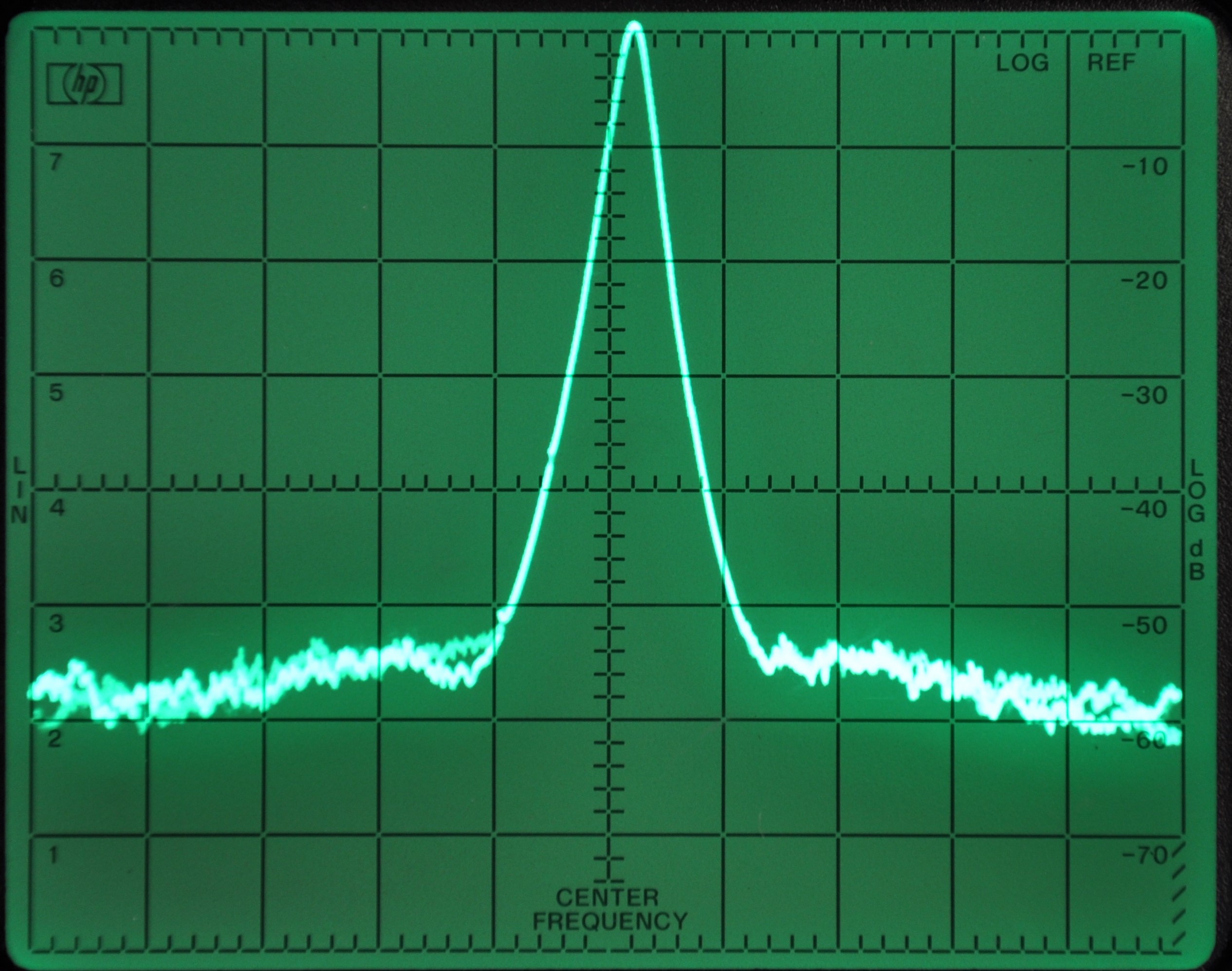
Examples of the expected performance of the Ettus B210 SDR transceiver are reflected in Figures 3 and 4. These figures illustrate the phase noise and transmit two tone IMD measured at 5.8 GHz. The phase noise measurement compares well to the phase noise of a precision 100 MHz comb generator. The phase noise of the SDR transmitter approaches the phase noise limitation of the HP spectrum analyzer. The IMD measurement uses the ARRL measurement approach and displays a ratio of over 50 dB of signal to 3rd order products. Typical transmit RF output >> +5 dBm, and the receiver noise figure of ~3+ dB. This performance level is broadly maintained across the 9-band transceiver frequency range of operation, 50 MHz through 6 GHz. The combined performance of the SDR hardware and real time, low latency, DSP software make it possible for the amateur to build high performance VHF through Microwave transceivers for home or rover operation.
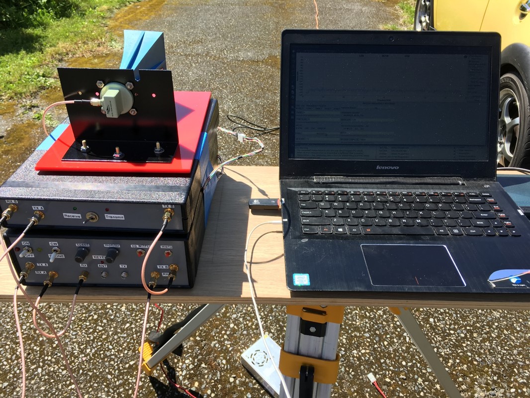
The 9-band microwave SDR station: The core microwave SDR transceiver evolved to become a complete VHF/microwave SDR station. Figure 5 shows two stacked enclosures: the 9-band SDR station housed in the bottom enclosure, and a 10 GHz and 24 GHz transverter contained in the upper enclosure. This photo depicts the arrangement for 10 GHz rover operation. The 10 and 24 GHz transverter can be rearranged for 24 GHz operation or disconnected from the 9-band station altogether, depending on the band to be operated. The 9-band SDR station is flexible, compact and self-contained. The same SDR radio is at home as a rover and at a fixed station.
The interior of the 9-band SDR station enclosure is shown in the busy photo, Figure 6. The style of the less than perfect construction reflects the slow development of the station from the basic SDR transceiver to a complete VHF/microwave SDR station. The enclosure contains the core Ettus B210 SDR transceiver, a Pic CW keyer and CW beacon, a relay sequencer (all in the stack of green PCBs in the lower right hand corner), a 10 MHz double oven master clock oscillator (the silver cube in the upper right hand corner), a receiver front end protection relay, a FM broadcast band reject filter (both the filter and relay buried under the wiring just to the left of the 10 MHz clock oscillator), a high power microwave antenna change over relay (the large silver rectangle in the center left of the chassis against the front panel at the left), and power distribution and control system for peripheral RF devices.
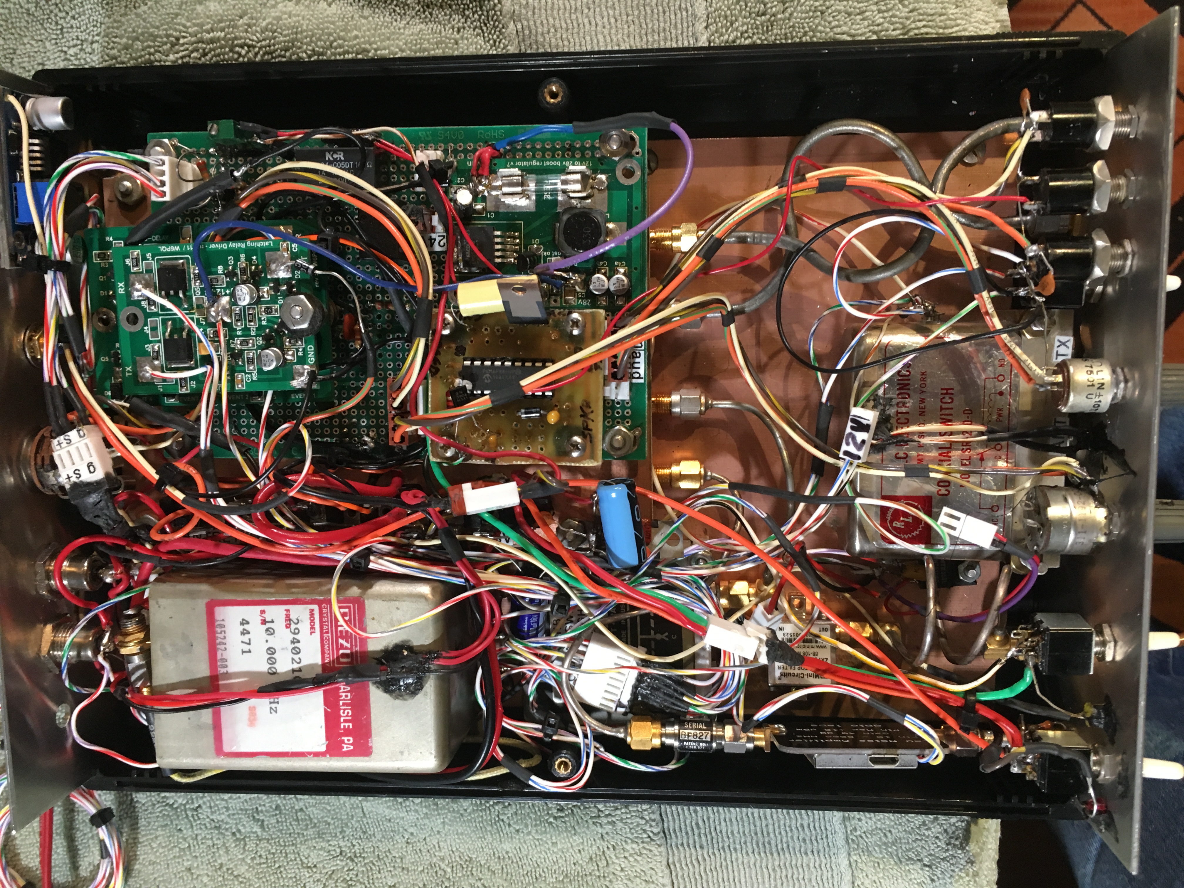
The high stability 10 MHz double oven clock oscillator was chosen as an inexpensive reliable alternative to a GPS disciplined oscillator. Frequency accuracy and stability are more than adequate for successful microwave communications. Either clock source would work perfectly well, if GPS access is not a problem in some operating situations. The receiver protection relay terminates the SDR transceiver receiver input port during transmit with a 50-ohm microwave termination. This precaution reduces the risk of receiver damage when transmitting with outboard higher power microwave PAs. (Ask me how I know) The FM broadcast band reject filer is necessary in our RF dense local environment to reduce RFIC A/D converter overload, especially when operating with vertically polarized and broadband antenna systems. The integrated high-power microwave antenna change over relay simplifies overall station configuration and eliminates yet another external peripheral from the station mix.
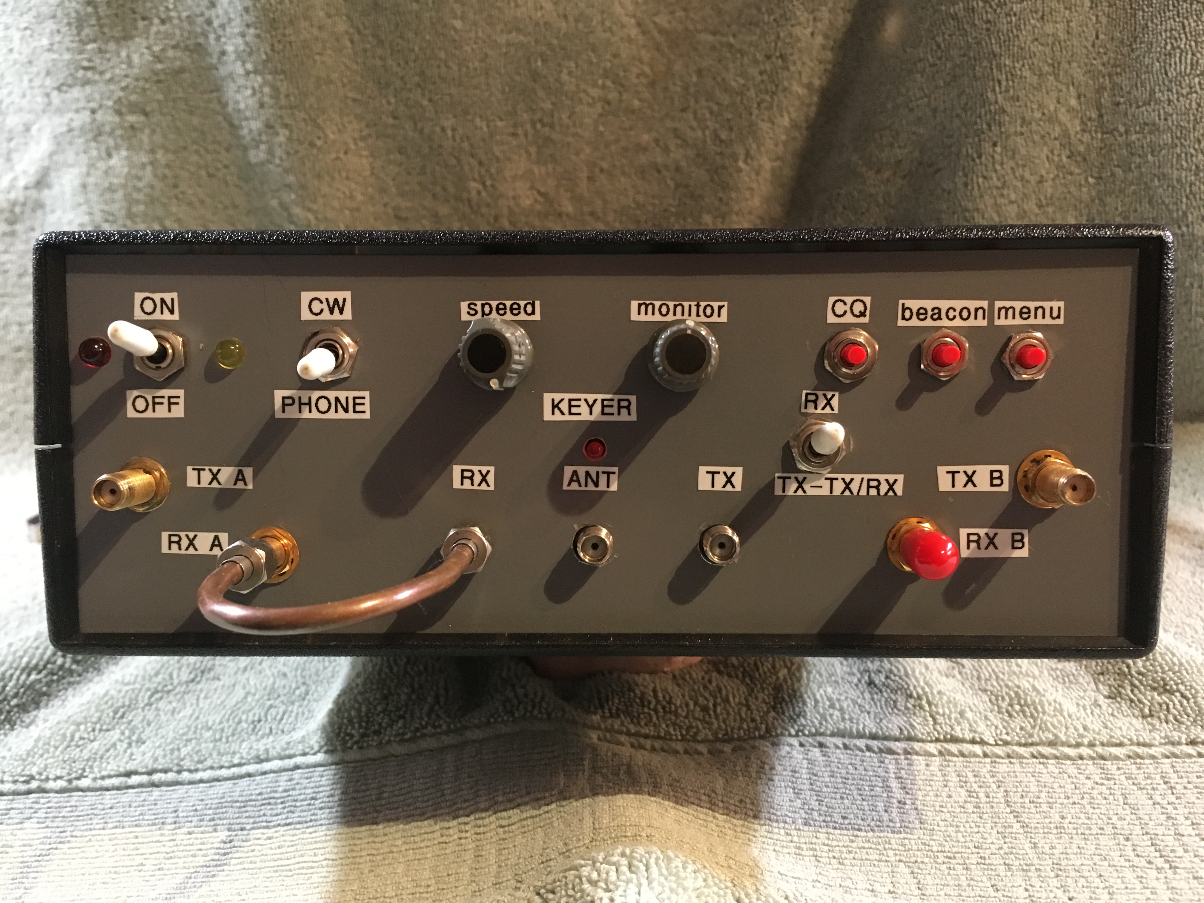
The front panel photo, Figure 7, captures, in a single image, the operational flexibility of the 9-band SDR station. Controls for power, mode selection, TX/RX control for outboard transverters and the Pic keyer functions are visible. The panel SMA coaxial connectors connect directly to the core SDR transceiver circuit board and to the internal microwave antenna change over relay. The RF ports on the panel can be patched with coaxial cable to permit flexible RF interfacing with the usual RF peripherals such as an LNA, remote antenna relay, and transmit power amplifiers, and outboard transverters (Figure 5). For instance, a higher power band specific PA can be patched between the transceiver TX A output and the antenna change over relay TX input to increase the transmit power. In a similar manner, a band specific remote low noise preamplifier can be included for a an operating situation. For test and measurement use, the transmitter and receiver ports are separately available at the front panel. The receiver port(s) can be separated and used as the RF input for microwave spectrum analysis with appropriate DSP software. In a similar fashion, the transmitter port(s) can be separated and used as a VHF/microwave signal source or an LO output, determined by the DSP software. The RF ports allow access to the two transmitters and two receivers from each of the two on-chip RFIC transceivers for other uses, not described in this article. (The 10 GHz transverter uses both SDR transceivers: one transceiver to provide the LO to the 10 GHz mixer and the other transceiver for the 5 GHz IF chain.)
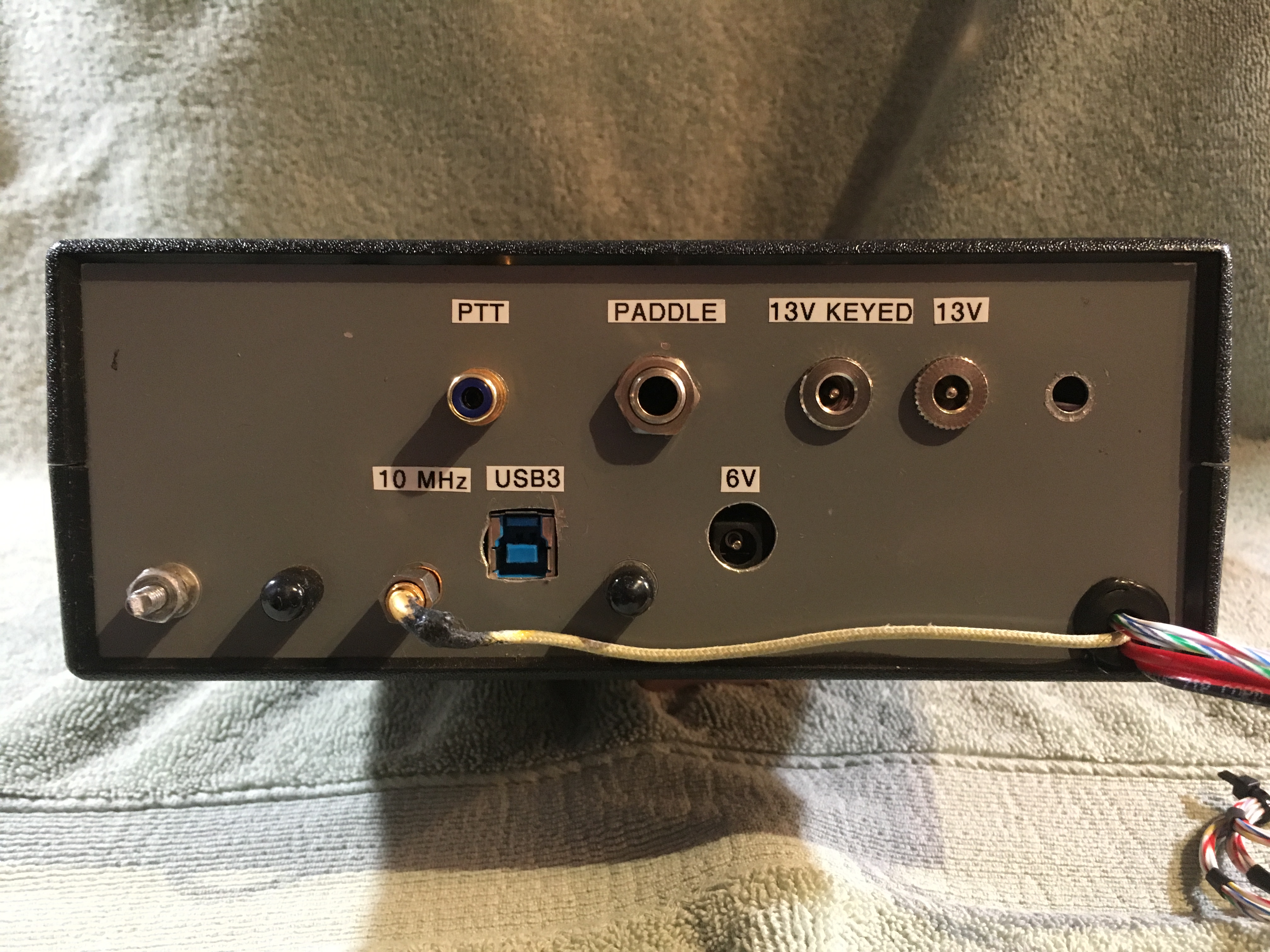
The back-panel, Figure 8, provides PTT control, CW paddle input, keyed and unkeyed 13.6 Vdc outputs, the USB3 computer interface, and 10 MHz master oscillator input. The back-panel connections provide a convenient source for powering band specific RF peripherals (preamplifiers and PA’s), and for keying and PTT control of transmit amplifiers as well as other station accessories for rover or home station use.
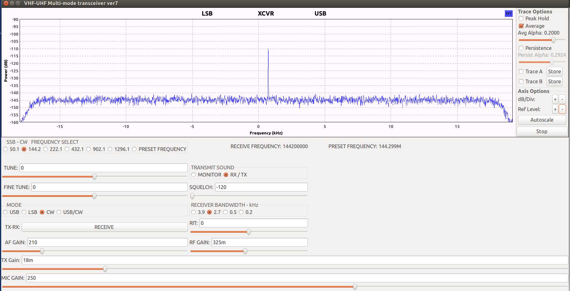
Interface with the DSP: Operation of the 9-band SDR is with a computer that is running DSP software, Figure 9. A USB3 cable connects the SDR and the computer. The on-screen operating user interface is depicted in Figure 10. This example interface is a visually simplified version for operation in the VHF and UHF spectrum. A second interface is used only for the microwave band, 1.296 GHz to 5.76 GHz, operation. The full 9-band operating range interface could also be included in a single computer display at the price of a visually more complex operating interface on the screen. A panadapter is the default frequency display. That said, the software can easily be configured to display only a panadapter or only a waterfall output, or both outputs simultaneously, chosen by the user. Visible in the photo are band selection, frequency tuning, mode information, and other standard radio controls. See Part 2: SDR DSP Software for additional details.
The SDR station and homebrew opportunities: The station description and computer interface display hint at the homebrew opportunities available to the builder. The construction of this homebrew station is based on modular design principles. The station began with the basic SDR transceiver board, as the heart of the station. For increased RF performance it was necessary to expand on the foundational SDR platform and finish out the RF components. A practical radio for general use was built to include the addition of an outboard band specific low noise preamplifier, power amplifier modules, filters, and other hardware modules that extended the RF utility of the basic SDR platform. A complete SDR station resulted with the addition of a precision clock source, system control circuitry and accessories, such as a keyer, a beacon, antenna change over relays, sequencers, among other items. All are included into a single enclosure. The only peripherals being the power supply and keyer paddle. Many homebrew opportunities simply evolved. Other possibilities exist.
Higher microwave band operation: In addition to functioning as direct conversion 9-band SDR transceiver, this transceiver is used as an arbitrary frequency IF for my 10 GHz, 24 GHz, and 47 GHz transverters. A single conversion scheme for higher frequency operation, built around the SDR station, leverages the broad band direct conversion SDR architecture to offer flexible IF choices that suit design goals of the builder and the microwave hardware available.
Part 2: SDR DSP Software
The other homebrew opportunity for the SDR builder is customized DSP software that meets the builder’s needs. The homebrew DSP software used for the 9-band SDR station is discussed here. Software development is unfamiliar territory and a source of anxiety for many hams. That said, “ham friendly” software that uses a graphical programming interface is available for the interested hobbyist. Good news for the homebrew hobbyist, is the software DSP is as flexible and open to innovation as are the hardware choices. Many, if not most, aspects of the DSP software are arbitrary and open to the builder’s ideas. For instance, the operating interface, illustrated in Figure 10, is completely arbitrary and can be customized to suit the builder. The DSP software could be built to support FM, or AM, or the digital mode operation in addition to, or instead of, this project’s SSB and CW DSP.
Overview: All SDRs require digital signal processing (DSP) to process the information on radio signals. Traditionally, all analog radios require analog components to process information on radio signals. ‘Signal processing’ includes adding signal information (modulation), such as with a transmitter, or extracting signal information (demodulation) such as with a receiver. SDRs perform the same information mod/demod functions in the digital realm as traditional analog radios do in the analog realm. “Signal processing is signal processing”. No different in principle with analog and digital systems. An analog radio block diagram can translate to a DSP block diagram in the GNU Radio DSP programing environment.
From Block diagram to DSP Software: If you can draw a block diagram for an analog radio, you can author DSP software for SDRs. GNU Radio and the included GNU Radio Companion (GRC) software development tool is an open source, no cost, DSP library, suitable for amateur homebrew DSP software. The GNU Radio software design tool has the advantage of being especially “ham friendly” when the DSP programming is accomplished with its graphical programing interface, GNU Radio Companion (GRC). With GRC, the mathematical algorithms, DSP functions, are depicted on the computer screen as rectangular blocks with input and output ports. The ports are digitally connected on the screen with line arrows, just like a traditional block diagram. This graphical method of programming is different and more user friendly than traditional command line programming.
The GNU Radio DSP library is a collection of already written math algorithms that perform specific DSP functions, filtering for example. To program with GRC, the user removes the desired DSP functions, one at a time, from the on-screen library to a center screen work area to compile a composite DSP function, SSB demodulator for example. The DSP functions are logically linked with lines and arrows. Any logical interconnected collection of DSP algorithms for a specific DSP process, SSB demodulator, is called a ‘GRC flow graph’. Connecting the GRC flow graph DSP software to appropriate SDR hardware creates a complete radio. Figure 11 shows the GRC flow graph and DSP for the 9-band SDR transceiver. The GNU Radio DSP library is fully capable of supporting most amateur radio communication needs for real time SDR operation.
DSP Software Competency: The journey to GNU Radio, GRC and DSP competence is not a simple process. Multiple on-line resources are available for learning. I recommend starting with my website: www.W7FU.com The website is entirely devoted to homebrew SDR. Of particularly relevant to the 9-band SDR transceiver are the menu choices: GNU Radio, SDR Projects and Presentations and Publications. The GNU Radio menu contains homebrew narratives and video content to guide the beginning user in a practical, ‘step by step’, approach to creating GRC flow graphs, literature references to DSP, and aggregates internet links to a range of on-line teaching resources. The SDR Projects and Presentations and Publications menus contains descriptions, as narratives or conference presentations, of a number of modern SDRs applications. The SDR Projects portion includes downloadable GRC flowgraph DSPs that can be run with the GNU Radio application.
Fn. 1: https://www.ettus.com/product
Fn. 2: https://www.redpitaya.com/
Fn. 3: https://myriadrf.org/projects/limesdr/
Fn. 4: https://greatscottgadgets.com/hackrf/
More information on SDR and GNU Radio topics can be found at: www.W7FU.com