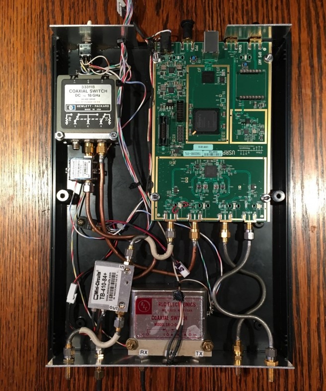
The RF Interface for the Ettus B210 VHF through Microwave SDR is a complex affair with some unique aspects. The goal of an interface is to package all the necessary peripheral components that are necessary to make the SDR a functional rig for on-the-air operation.
The photo depicts the basics of a VHF/Microwave RF interface. The green PC board butted against the rear enclosure panel is the Ettus B210 SDR transceiver. The coaxial switch in the upper left-hand corner is the receiver protection relay. For receive operation, this relay connects the receiver input of the SDR board to the receiver SMA coaxial connector on the front panel. In the transmit mode, the relay disconnects the receiver terminal from the panel connectors and shunts the receiver input with a 50 ohm microwave termination. This relay protects the receiver from microwave leakage and potential damage during transmit.
The small gold colored module connected to the protection relay is the FM broadcast band stop filter. This filter is useful to reduce cross modulation in the otherwise ‘wide open’ A/D converter of the SDR.
Further down the photo, on the left-hand side, adjacent to the front panel, is a silver colored Mini-Circuits amplifier module. This broad band amplifier boosts the ~ 5 dBm output of the SDR transmitter to approximately 14 dBm, a value useful to drive peripheral power amplifiers: Power Modules
In the bottom center of the photo, is the microwave T/R relay with the SMA connectors projecting out of the enclosure front panel. This T/R relay function is shared with all the power amplifier modules and microwave transverters.
Link to Terms and Abbreviations: Terms and Abbreviations
Link to Home Page:Home Page