The Universal Multi-Mode Transceiver DSP demonstrates the Filter Method for signal processing of SSB signals, for transmit and for receive operation. Other methods for SSB signal processing, the Phasing Method and the Weaver Method (Quadrature Mixer), will not be presented in this project. An amazing property of SDR DSP is the ease with which universality is possible. The same DSP architecture can be incorporated into any number of SDR’s simply by editing a .grc DSP file. There are no wires to connect or components to be replaced. DSP’s can be modified or optimized on the fly by editing the DSP file. This DSP is the primary DSP for all of my rigs for HF through 79 GHz, portable, and home station operation. Separate .grc files for an HF transceiver (3.5 to 28 MHz), a VHF/UHF transceiver (50 to 1296 MHz), and a Microwave transceiver (902 to 5700 MHz) are presented for download. The differences among the DSP files are the parameters chosen for the frequency control of the SDR hardware in use. These .grc files could be edited to produce a ‘mega’ Operating GUI that covers all the amateur bands. That said, such GUI would be very complex and not as easily navigated as the present GUIs that present the spectrum of potential SDR operation in smaller logical segments.
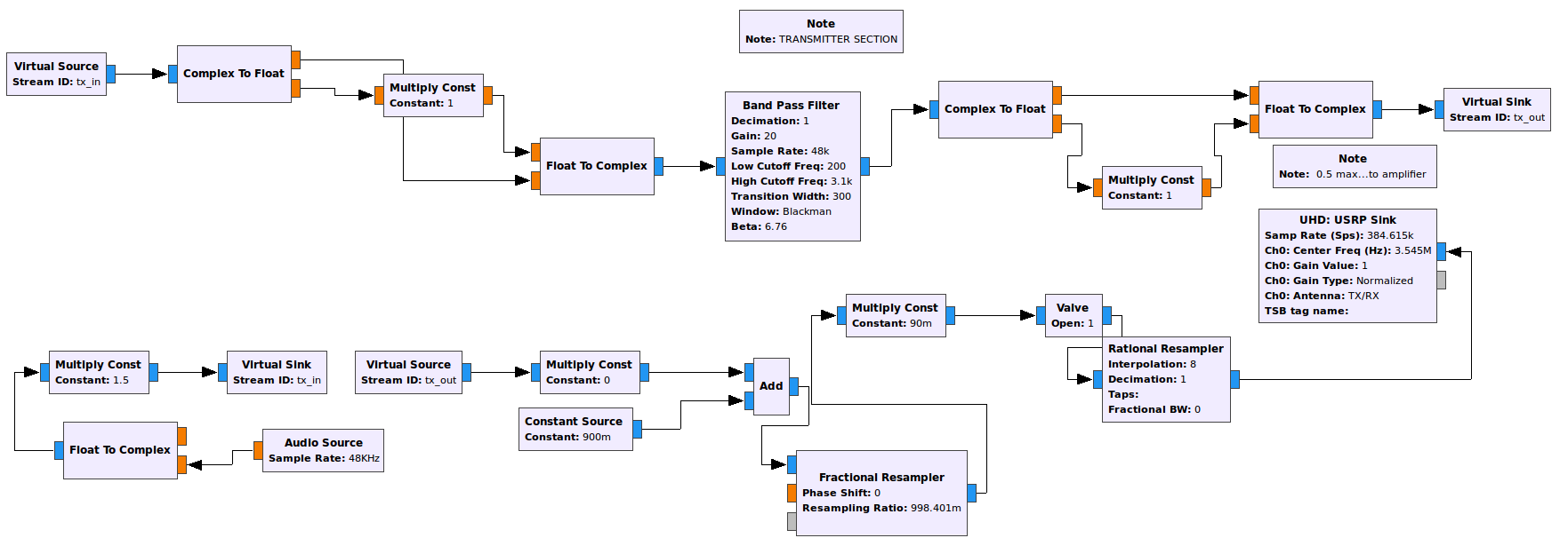
The GNU Radio flowgraph for this transceiver is rather complex. To represent the flowgraph in an approachable manner, the flowgraph functional units will be represented as a series of three screen captures: the Control section, the Receiver section, and the Transmitter section. The flowgraph illustrates some advanced DSP and GNU Radio authoring techniques. Some of these techniques will be mentioned but not explained in detail. Further understanding will be left to the reader by study of these resource: Bibliography
The Control section of the flowgraph is populated by WX GUI Sliders and WX GUI Choosers, linked entering the control block ID string into the DSP function block parameter to be adjusted as described here: How To: link Control blocks with DSP blocks

The receiver segment of this flowgraph depicts some advanced GNU Radio authoring techniques. The Virtual Source and Virtual Sink DSP blocks eliminate some of the data link lines (black lines with arrow heads) in the flowgraph for increased visual clarity. This technique, the Virtual blocks, are utilized to locate the Complex Filter DSP, shared between the receiver and transmitter portions of the the flowgraph to be represented in the transmitter segment of the flowgraph. Sharing the Complex Filter DSP in this manner further simplifies the depiction of the flowgraph.

The transmitter segment of the flowgraph contains the Complex Filter DSP that is shared with the receiver segment. The transmitter DSP allows CW and selectable SSB operation.

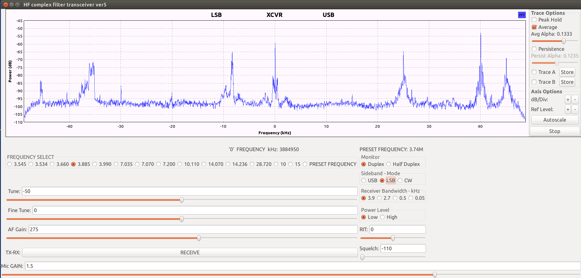
When the .grc file is executed, the Operating GUI appears. Note the panadapter display across the top of the GUI and the multiple operating controls. These controls provide for a pleasing operating experience.

To illustrate the flexibility of the Universal Multi-Mode Transceiver DSP, I am including two short screen capture files of on-the-air reception using this universal DSP. These screen captures were recorded via the Universal Multi-Mode DSP by selecting the appropriate SDR in order to change bands. These files capture QSO’s on 144.2 MHz SSB: 144.2 MHz SSB QSO and another QSO on 3.545 MHz CW: 3.545 MHz CW QSO
The procedure for downloading the .grc files for this project is here: Downloading .grc files The .grc files for this project are here: HF Complex Filter Multi-Mode Transceiver.grc, B210 Microwave Multi-Mode Transceiver.grc, B210 VHF-UHF Multi-Mode Transceiver.grc
Link to Terms and Abbreviations: Terms and Abbreviations
Link to Home Page: Home Page